plasmotek@plasmotek.com
+91-9845681205

Injection mould design
Injection Mould Design: Key
Principles, Specifications & Best Practices
Injection mould design is one of the most critical stages in the plastic
part manufacturing process. A well-designed mould ensures product quality,
dimensional accuracy, repeatability, and cost efficiency. Whether
you’re developing a simple consumer item or a complex automotive component, a
robust mould design is essential to achieving consistent, defect-free
production.
In this blog, we’ll explore the fundamentals of injection mould design,
important specifications, design considerations, and answer frequently asked
questions to help guide your next tooling project.
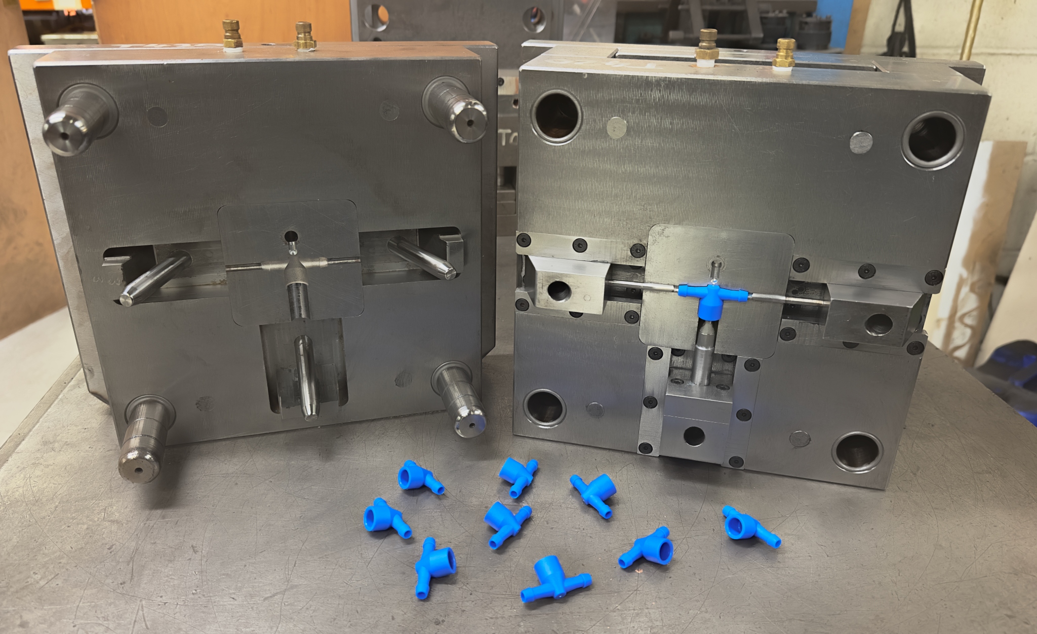
What is Injection Mould Design?
Injection mould design refers to the engineering and structuring of
moulds used in plastic injection moulding. The mould is a custom-fabricated
tool that shapes molten plastic into a solid form when injected under pressure.
A typical injection mould includes core and cavity plates, cooling
channels, runners, gates, and ejector systems. The design of these elements
directly impacts cycle time, part quality, cooling efficiency, and mould
life.
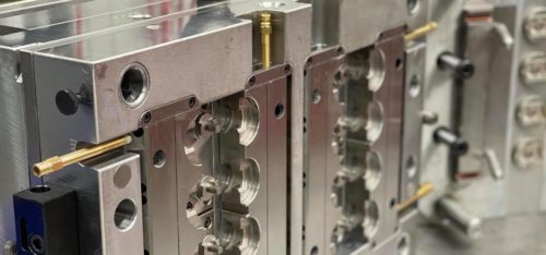
Types of Injection Moulds
Understanding the different types of moulds is crucial when initiating a
tooling project:
1. Two-Plate Mould
The most common type, ideal for simpler parts. The mould splits into two
halves — one fixed and one moving.
2. Three-Plate Mould
Features an extra plate to allow easier ejection and more flexible gate
placement, typically used for more complex or multi-gated parts.
3. Hot Runner Mould
Uses heated channels to maintain molten plastic within the runner system,
reducing waste and improving cycle time.
4. Cold Runner Mould
Allows the plastic in the runner to cool and solidify with each cycle.
It's cost-effective but creates more waste.
Specifications of a High-Performance
Injection Mould
Here are key technical specifications and design elements that define a
reliable injection mould:
|
Specification |
Typical Range / Description |
|
Mould Base Material |
Tool Steel (P20, H13), Aluminum |
|
Core & Cavity Material |
Hardened Steel, Stainless Steel |
|
Mould Life |
100,000 to 1,000,000+ cycles |
|
Cooling System Efficiency |
Optimized with baffles, channels, or conformal cooling |
|
Tolerance Capability |
±0.01 mm to ±0.05 mm |
|
Ejection System |
Ejector pins, sleeves, lifters, stripper plates |
|
Gate Types |
Edge gate, Pin gate, Valve gate, Submarine gate |
|
Surface Finishes |
VDI, SPI, EDM textured, high-polish |
Key Considerations in Injection Mould
Design
Designing a mould involves a balance between function, durability, and
manufacturability. Below are the essential design factors:
1. Part Geometry
Understanding the shape and complexity of the part is critical. Sharp
corners and uneven wall thicknesses should be avoided to reduce stress concentrations
and improve flow.
2. Wall Thickness
Uniform wall thickness ensures consistent cooling and reduces defects
like warping or sink marks. Aim for walls between 1 mm to 4 mm,
depending on the part size and material.
3. Draft Angles
Include draft (typically 1° to 3°) to facilitate easy part
ejection from the mould without damaging the part.
4. Cooling Channel Design
Efficient cooling is essential for reducing cycle time and improving part
consistency. Use optimized baffle and channel placements to evenly cool the
mould.
5. Material Selection
Choose the right material for the mould components based on the expected
production volume, cycle time, and type of plastic being moulded.
6. Venting
Proper venting prevents trapped air and gas burns. Vents should be
strategically placed in low-pressure areas.
Common Challenges in Mould Design
Even experienced designers encounter issues. Here are some common
problems and how to avoid them:
- Short Shots: Caused by
inadequate venting or poor runner design.
- Flash: Results from
excessive injection pressure or worn parting lines.
- Warping: Uneven
cooling or inconsistent wall thickness.
- Sink Marks: Thick
sections that cool slower than surrounding areas.
Early collaboration between the product designer and toolmaker is key to
solving these issues before production begins.
FAQs About Injection Mould Design
Q1. How long does it take to design
and build an injection mould?
A: The design phase typically takes 1–3 weeks, while mould fabrication can
take 4–8 weeks depending on complexity and revisions.
Q2. What’s the difference between
prototype and production moulds?
A: Prototype moulds are usually made from aluminum and built quickly for
low-volume testing, while production moulds use hardened steel for durability
and mass production.
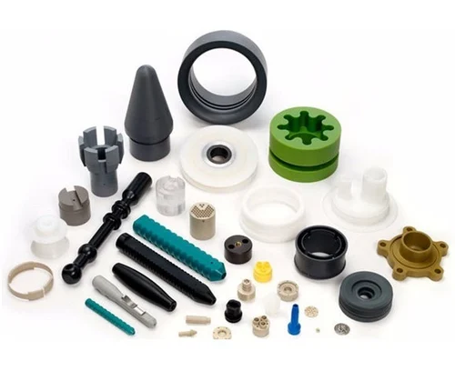
Q3. Can a single mould produce
multiple parts?
A: Yes, multi-cavity moulds are designed to produce multiple identical
parts per cycle, while family moulds can create different parts in the same
mould.
Q4. How do I choose between a hot
runner and cold runner mould?
A: Choose hot runners for high-volume, waste-reduction, and better flow
control. Cold runners are simpler and more cost-effective for lower-volume
applications.
Q5. What software is used for mould
design?
A: Common tools include SolidWorks, Siemens NX, AutoCAD, CATIA, and Moldflow
for simulation and analysis.
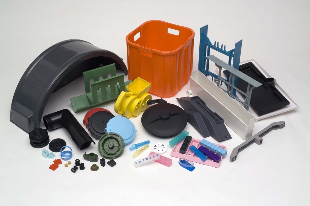
Final Thoughts
Injection mould design is the foundation of any successful plastic injection
moulding project. A well-designed mould can improve product quality, reduce
production costs, and extend tool life dramatically.
Investing time in mould design, simulation, and collaboration with skilled toolmakers pays off in the long run. Whether you're building a single prototype or launching mass production, understanding the principles of mould design helps you make smarter decisions for your product and business.